ASTHRA
IN-SITU HAND DRIVEN ID CLAMPING FLANGE FACER

We, at Shenoy Engg. Pvt. Ltd. manufacture In-situ, portable Electro-Mechanical Flange facers. These flange facers are mainly used in for generating smooth or serrated finish on the flange butting surface. We have supplied these flange facers to various companies and they are performing to the customer’s satisfaction.
Based on the feed back from the users of our electro-mechanical flange facers, there is a need for a flange facer which should be compact and light weight. It should be easily to carry and power source required for operation should be easily available.
We took all these factors into consideration and developed a Hand Driven Flange Facer. 70% of the flange facer is made of aluminum which make it light and is hand driven which eliminates the need for any power source, be it electricity, hydraulics or pneumatic. Since this does not involve any powered source except for human power, this product is fire hazard free and most ideally suited for petroleum, chemical refineries.
This flange facer has a facing range from 25 mm to 310mm i.e. 1” to 12” and has a clamping range of 1” to 6”. The main components of this facer like arm, housing, is cast from Aluminum to make it light. This whole unit weighs under 8 Kgs. Sliding surface is made of LM guides and blocks to provide utmost frictionless smooth movement, keeping in mind the operator’s fatigue. The tool is moved over the LM guides through a leadscrew-box nut arrangement coupled through a worm reduction gear box. The input of the worm reduction gear box has a knob which can be rotated. The box nut is made of phosphorus bronze which creates less friction against the lead screw while rotating. The tool is provided with a single point cutting tool of cross section 10×10 mm. The flange facer will be provided with tool holder have standard ISO carbide inserts, which are easily available in the market. The arm on which the slide unit is mounted is connected to rotatable housing. A case hardened hollow spindle is supported by two deep groove ball bearings inside the housing to provide sufficient stiffness against the radial cutting loads while facing. Inside the hollow spindle, a threaded clamp shaft is provided. The spindle also has 3 slots, where 3 jibs can be mounted. When the clamp shaft is rotated, a taper provided on the shaft pushes the jibs out of the slot equally thereby clamping the facer inside the bore and self-centers the Flange Facers.
| Specification: | Inches | Millimeter |
| Facing Range | 1” to 12” | 25.4 mm – 304.8 mm |
| Clamping Range | 1” to 6” | 25.4 mm – 152.4mm |
| Tool Vertical Traverse | 1” Manual through fine pitch bolt | 25.4 mm Manual through fine pitch bolt |
| Tool Post Swivel | ±45° | |
| Tool | Single point cutting tool with indeaxble Standard Carbide inserts | |
| Maximum Depth of cut | 0.2 mm or 0.007” | |
| Finish Obtainable | Serrated Finish and smooth finish by changing of gear box. | |
| Slides ways | LM Guides of HIWIN make | |
| Gearings | 2 No.s of SKF make deep groove ball bearings. | |
| Drive | Hand Driven through worm reduction gear box coupled to lead screw and phosphorus bronze box nut | |
| Clamping | By self-centering jibs – Through tightening of threaded clamp shaft | |
| Jibs | Detachable jibs given in incremental sizes. Held to each other through screw | |
| Jib locking in Spindle | Through O-rings | |
| Targeted Market | Piping, refinery, ship building, maintenance work | |
Video:
IN-SITU HAND DRIVEN OD CLAMPING FLANGE FACER
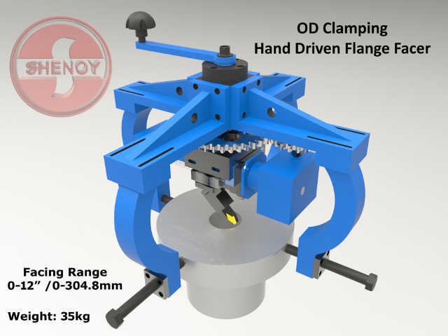
| Specification:Inches | Millimeter | |
| Facing Range | 0 to 12” | 0 mm – 304.8 mm |
| Clamping Range | 3” to 12” | 76.2 mm – 304.8 mm |
| Tool Vertical Traverse | 1” manual through fine pitch bolt | 25.4 mm manual through fine pitch bolt |
| Tool Post Swivel | ±45° | |
| Tool | Single point cutting tool with indeaxble Standard Carbide inserts | |
| Maximum Depth of cut | 0.2 mm or 0.007” | |
| Finish Obtainable | Serrated finish and smooth finish by changing of worm reduction gear box. | |
| Slides ways | LM Guides of HIWIN make | |
| Bearings | 4 No.s of FAG make deep groove ball bearings. | |
| Drive | Hand Driven through spur gear combination with worm reduction gear box coupled to lead screw and phosphorus bronze box nut | |
| Clamping | Through tightening of threaded studs | |
| Leveling | Manually through M16 threaded bolts provided on the legs of the facer | |
| Weight | Approximately 35 kg | |
If you are interested, please feel to contact us.
Contact:
Shenoy Engg. Pvt. Ltd.
#7, 16th Cross, Doddanna Industrial Estate
Near Peenya 2nd Stage, Bangalore – 560 091
India
Ph: +91-80-2836 1767; +91-80-2836 1725
Website: www.shenoyengineering.com
Email: info@shenoyengineering.com
Contact us for product information
Contact Details
- +91-80-28361767
- info@shenoyengineering.com
- +91-80-28361725